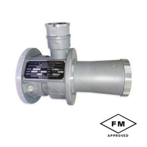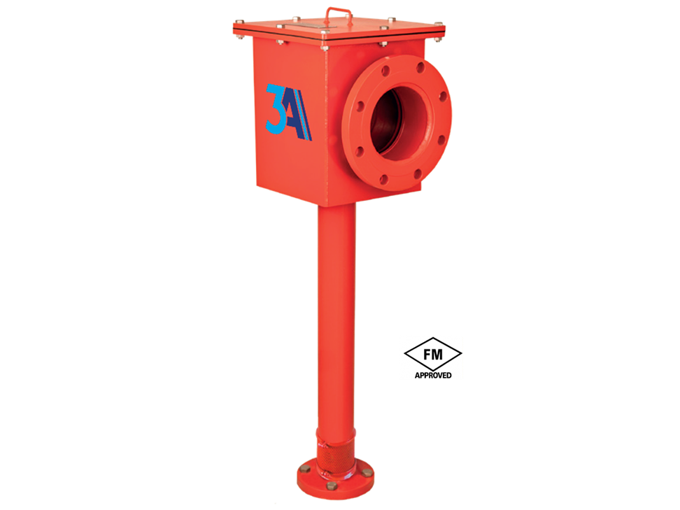
Foam Chamber General Specifications:
DN50, DN65, DN80, DN100 and DN150NB connection diameter
100 – 1800 l/min (26 – 476 GPM) calibration range
Carbon Steel or Stainless Steel material
Working pressure 2.8 – 7 Bar (40 – 100 PSI)
Epoxy painted inside and outside
Stainless Steel calibration plate
Fuel vapor locked
Routing Shield
FM Approved
*Foam Chamber unit with DN50 connection is not FM certified.
Depending on the diameter of the tank, the number and capacity of the foam chamber to be used is determined in accordance with the design standard. In addition, according to the type of flammable and combustible material, the number of minutes of continuous foam application should also be calculated.
In order for the foam chamber system to work effectively, the pressure loss of the pipe network must be carefully determined using a hydraulic calculation program. The Foam Chamber to be supplied must be calibrated at the manufacturer’s facility taking into account this calculated pressure value and presented to the end user with the calibration certificate.
In addition, each product must include a fuel vapor lock. The Fuel Vapor Lock must prevent flammable vapors inside the tank from escaping from the Foam Chamber air inlet or filling into the pipe network.
These products must be regularly testable. Foam chambers can be manufactured in classic black material or stainless steel for durability and long life. Although stainless steel models have a higher initial cost, they can be more economical in the long run as they are more resistant to corrosion.
Choosing the right materials and equipment in fire protection systems is critical to minimize the loss of life and property in case of fire. Therefore, the use of standardized and certified products alone is not enough, regular maintenance and testing must also be planned and periodically implemented.
Related Products